Tunnels are well-established for transporting goods and people. They help reclaim land by moving transport underground, reducing noise, shortening transport routes, and minimizing traffic jams. For public transport in bigger cities, tunnels are often the only option. However, new tunnel construction requires concrete, which is known to significantly contribute to global warming due to its inherent CO2 emissions during production.
This paper presents considerations for minimizing concrete use and its related CO2. Owners and designers must take responsibility and establish CO2-saving targets early in the project. As concrete and its “glue” cement dominate the CO2 of new tunnels, early project considerations can focus on this main contributor, choosing the proper excavation method and applying modern and innovative design solutions. Material suppliers and construction companies follow their proposed path. Environmental optimization at a later project phase is less efficient and more costly.
This paper demonstrates the CO2 related to concrete and established tunnel excavation methods, which are not always interchangeable. However, transparency highlights the potential for improvement in carbon savings.
1. Introduction
As concern over diminishing resources and climate change grows, sustainability has become a top priority. While demand for eco-friendly materials and construction methods is rising, sustainability remains a secondary consideration in underground construction projects.
Sustainability involves balancing economic, environmental, and social factors. A solution can’t be considered sustainable if it focuses on just one of these pillars; it must consider all three. This balance evaluates the impact of materials and practices throughout their entire life cycle, identifying and mitigating any adverse effects that may arise at different stages.
Selecting sustainable materials can significantly reduce carbon emissions, but is that enough? Should a broader approach, including changes in construction processes, energy sources, and overall project management, be required to tackle carbon reduction? Thus, while materials play an essential role, we must investigate the larger context of tackling sustainability in tunnels.
Tunnels are built in rock and soft ground so that the ground can support the load redistribution caused by the tunneling works. However, concrete is needed as the main building material to assist and deal with weaker ground.
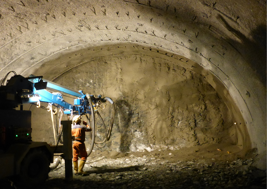
Tunnels excavated with the conventional cyclic method use a drill-and-blast approach, often called NATM (New Austrian Tunneling Method, see Figure 1). Sprayed concrete is the primary support, and an accelerator ensures it sticks to the wall and gains rapid strength. Cast concrete comes significantly later as the final support.
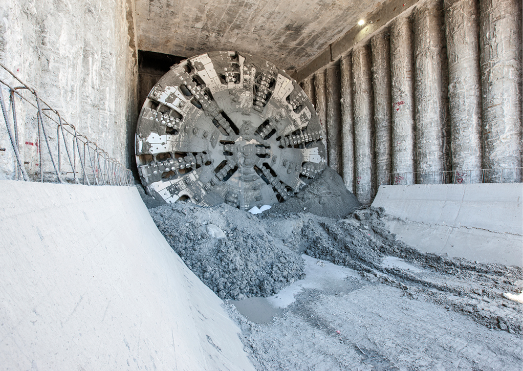
Continuous tunnel excavation is achieved by employing tunnel boring machines (TBMs, see Figure 2), big and very long machines that cut a circular hole in the ground. The first support is provided by a machine shield, followed by cast concrete elements as final support, called segments, that are put in place by erectors. A grout fills the gap to the ground to provide sufficient load transfer.
CO₂ is commonly known as the major contributor to global warming. However, other greenhouse gases act similarly, represented by the term CO₂e. Therefore, when we refer to CO₂ in this paper, we are speaking of all contributors.
3 Opening considerations
Can carbon-neutral tunnels be achieved through materials alone? This paper’s title implies that carbon savings must balance carbon allocated to tunnel construction; otherwise, neutrality cannot be achieved. These savings mainly come from reduced transport distances and reduced energy consumption from flatter gradients in case of mountain crossings by car or train, fewer traffic jams and shorter routes in the case of bypass tunnels, or a functioning public transport system via subways.
However, the CO2 emissions from construction are emitted today, contributing to global warming. The balance to achieve neutrality is achieved over the years afterward. The key question to be answered is whether it makes sense to build a tunnel when carbon neutrality is the only decisive factor and other benefits like regaining land and reducing noise and pollution are neglected.
A perfect answer to this can be found in a paper from Haist et al., where the Climate Limit State (CLS) was introduced [1]. This potential design criterium, comparable to the well-established Service Limit State (SLS) and Ultimate Limit State (ULS) in construction, addresses the abovementioned challenge. The politically established net-zero target and how much CO2 is left to achieve it are factors that guide the tunnel owner and designer to the right decision concerning Global Warming, that the construction CO2 investment is finally balanced by the transport savings to contribute in time to the political net-zero goal positively.
Literature reports that the total CO2, which can be attributed to new tunnel construction, is dominated by concrete and the related cement CO2, which account for about 2/3 of the total [2]. The apparent consequence is that any relevant CO2 reduction must address the total concrete volume needed for safe construction and tunnel utilization and favor CO2-optimized concrete mix designs.
Carbon saving at tunnel job sites can be successful if pragmatism prevails. Theoretically, any measure taken at the site impacts the total carbon output, but its contribution might be minor. To aim at considering all potential carbon impacts is most likely leading to a failure; one might get lost in detail and put too little attention on the significant contributors. Pragmatism is required; the Pareto principle should be favored. As mentioned above, the tunnel construction CO2 is dominated by concrete and its components, like cement, the main contributor, and steel. Therefore, this paper concentrates on concrete to catch the most essential CO2 source and highlights ways to reduce it.
Engineers build tunnels, and engineers love accuracy. The challenge is that 100% accuracy can never be achieved when calculating CO2 savings. The biggest lever for carbon reduction, in general, is an early consideration in the project design, but only a rough project plan and generic material data are available. Therefore, a pragmatic approach, including simplification, should be the goal at a very early project stage used for decision-making, and a more accurate evaluation is appropriate for documentation purposes as the project progresses. It is essential to distinguish between decision-making and documentation.
3 Current carbon influence by materials
With more than 14 billion cubic meters used each year, concrete is the most essential construction material of our time. It is impossible to imagine modern civil engineering and tunnel construction without it [3]. However, the cement content poses a significant climate problem because, during the production of the cement clinker, enormous amounts of CO2 are released into the atmosphere, accounting for approximately 8 % of all manufactured CO2 emissions worldwide annually [4]. Concrete CO2 reduction for tunnel construction is, therefore, a must! But how can this be evaluated and finally achieved?
The assessment of concrete GWP (Global Warming Potential) follows simple rules: The mass of the materials in one cubic meter of concrete is multiplied by the specific impacts reported in EPDs (Environmental Product Declaration). Certified software uses data from such EPDs and adds the CO2 emitted by production processes like mixing.
The focus should be on the most significant mass in the mix and high CO2 emissions per unit, which means cement (predominantly Portland cement clinker), steel, and chemicals (sprayed concrete accelerator). An Excel spreadsheet can also estimate quickly, providing reliable results with sufficient input parameters.
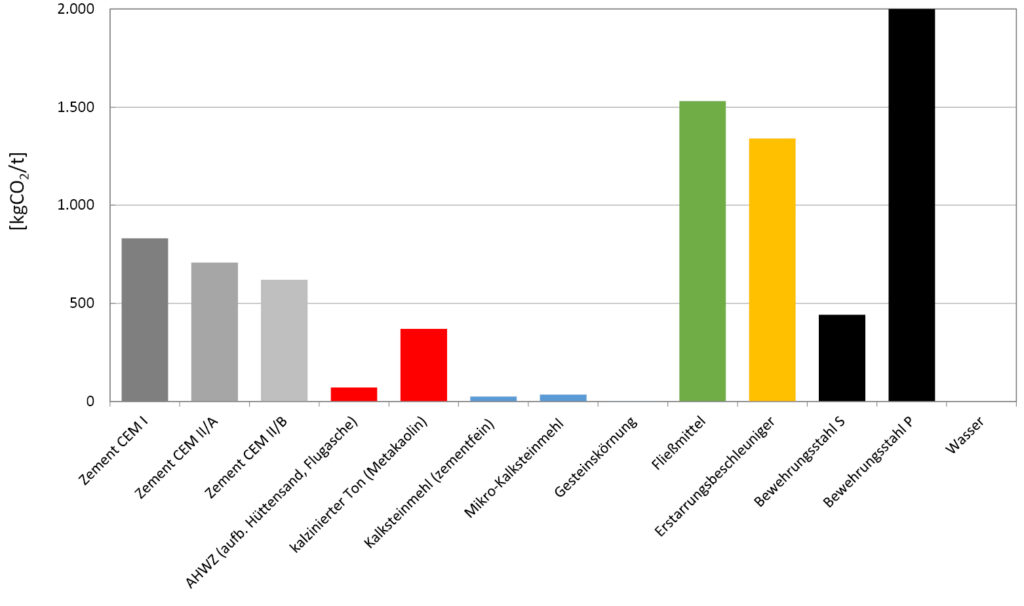
Figure 3 [2] shows the carbon footprints reported in EPDs for mostly Austrian-based construction materials. The CO2 impact of reinforcing steel can vary significantly depending on the production process and the proportion of recycled material; here, reinforcing steel S (recycled steel, steel produced in an electric arc furnace) is compared with reinforcing steel P (iron ore and coal, steel produced in a blast furnace).
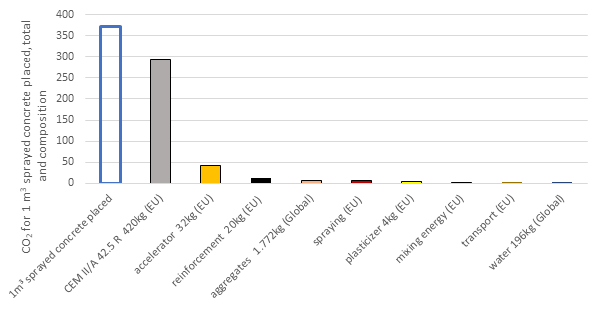
In Figure 4 the CO2 emissions per material used for 1 m³ sprayed concrete are shown, where cement dominates the total emissions. It should be noted that the mixing energy at the batching plant, transportation to the job site (in this example, 15 km), and spraying contribute very little to the total and can potentially be ignored in initial optioneering calculations.
Drill and blast tunnels are supported by sprayed concrete and cast inner linings. The GWP assessment for these structural concretes per cubic meter is shown in Figure 5 [6]. In this example, sprayed concrete is reinforced with a light steel mesh, and the inner lining is not reinforced, as in most Austrian tunnels. There is a clear indication that the cement content dominates the CO2 emissions.
4 Is design playing a role?
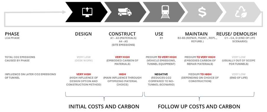
To quantify the environmental impacts, life cycle assessments (LCAs) according to ISO 21930 are commonly used to assure an objective analysis throughout the four main specific life cycle stages: production (A1-A3), construction (A4-A5), use (B1-B7), and the end-of-life (C1-C4). For tunneling projects, however, design should be added to these LCA stages because, despite its low direct CO2 impact, its influence on later emissions is dominant [7]; see Figure 6.
The CO2 evaluation of a project that should last 100 years is challenging since a balance must be found for the initial CO2 in the construction phase and the later effects of the solutions and materials used in the use phase, including refurbishment needs. It could also mean a higher CO2 consumption for the construction coming with higher quality and more durable materials (performance), allowing for reduced maintenance needs and less related CO2. In contrast, the worst case would be to completely close a tunnel for structural refurbishment due to low materials and construction quality and re-route the traffic for this period, generating additional traffic-induced CO2.
In most tunnel projects, key decisions are taken early. They may include checking and agreeing on variants, alignments, double vs. two single tubes, and excavation methods (TBM vs. drill and blast (NATM)). The factors above will significantly impact the total potential to reduce CO2 emissions and lower costs later in the project [7]. This means evaluations and decisions about reducing CO2 should be made as early as possible. However, this will counter and conflict with an exact life cycle assessment as the required project-specific data are not yet available. Therefore, pragmatism should prevail. Generic data are a good starting point for the first project decisions, but concrete EPDs should be as accurate as possible at this project stage.
In short, design plays the most critical role in CO2 savings, including the types of construction contracts agreed upon with the project owner [8].
The construction phase, however, significantly contributes to a tunnel’s overall environmental footprint during its life cycle. Therefore, the quality, specification, and amount of construction materials, such as concrete, should be carefully selected. As mentioned above, the paper from Haist et al. [1] provides guidance.
Although a holistic approach to preventing burden shifting is always recommended, the following examples limit the observation horizon to the production stage of concrete materials (A1-A3). This phase is the dominant CO₂ contributor during the construction and is related to improving understanding and providing food for thought.
5 TBM and NATM tunnel – CO2 per linear meter structural support
Below, the two common tunnel construction methods are compared. Both methods need completely different machinery with different related CO2 emissions. But this is neglected in the following considerations since it plays a minor role in total project CO2 [2, 9].
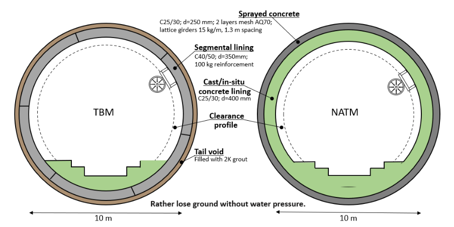
The TBM excavated 10 m diameter tunnel will be compared to the NATM tunnel with the exact inner dimensions (Figure 7). Since concrete dominates the tunnel construction CO2, the concrete volume per cross-section used and effectively placed impacts the overall CO2 emissions. The TBM tunnel is excavated with a nice round shape, hardly any unplanned breakouts from the ground (overbreak), and apparent volumes for the concrete. This document counts the grout for filling the gap from the machine overcut as concrete since it can contain a considerable amount of cement. Volumes for the segmental concrete and the gap grout are known and don’t differ from the design assumptions. Our example’s lining thickness is 500 mm (350 mm for the segment + 150 mm for the gap grout).
For the NATM-driven tunnel, it is entirely different. Geology more often dictates the thickness of the built lining and overbreaks must be filled with sprayed concrete. Since the lining is built in place and the minimum thickness as designed must be met, the built thicknesses differ significantly. To account for this, 150 mm has been added to the sprayed concrete and to the cast inner lining. The total lining thickness, being decisive for the CO2, amounts to 950 mm (150 mm + 250 mm (design) for the sprayed concrete, 150 mm + 400 mm (design) for the cast concrete). Of this, nearly 1 m thick concrete lining, only 400 mm of the inner lining is considered permanent in many design assumptions [2].
The resulting concrete volumes for these two excavation types are shown in Table 1.
Table 1 Concrete volumes per linear tunnel meter used for calculation
| Concrete volumes in [m³] per linear tunnel meter | TBM | NATM | |
| Gap grout / sprayed concrete | design | 5.1 | 8.9 |
| Sprayed concrete | extra | – | 5.5 |
| Sprayed concrete | rebound / waste | – | 1.5 |
| Segment / cast inner lining | design | 11.4 | 13.1 |
| Cast inner lining | extra | – | 5.2 |
| Total | 16.5 | 34.2 |
Concrete mix designs can be optimized for CO2. The best way is to reduce clinker, which is often possible, but a reasonable total clinker reactivity must be ensured to guarantee the buildability and functioning of the tunnel support.
In the example below, the standard mix designs from Figure 5 are optimized, where clinker was partly substituted by SCMs (supplementary cementitious material, mostly fly ash and ground blast furnace slag). A standard gap grout and segmental mix design from Austria was again taken and optimized by clinker reduction. It must be added that the gap grout was changed from an easy-to-handle 2-component version to the well-established old mono-component grout [2].
The pure material optimization results in the following CO2 reduction per meter cube, as shown in Figure 8 and Figure 9 below.
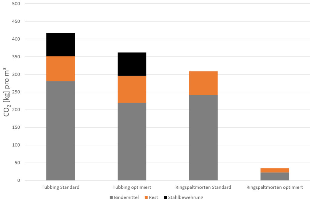

The above-evaluated actual concrete volumes (Table 1) are multiplied with the concrete-specific EPDs, as provided in Figure 8 and Figure 9. The standard concrete mix designs (TBM/NATM standard) and the optimized mix design (TBM/NATM optimized) are shown. An aggressive design approach was also used for the last scenario in Figure 10.
Before commenting on the results, it must be noted that the circular tunnel shape is unfair to NATM tunnel excavations since their excavation shape looks like an egg, meaning less excavated ground and concrete than for a circle. Additionally, shorter tunnels are not built with TBMs since the machine costs and delivery lead time are too high compared to NATM drive costs.
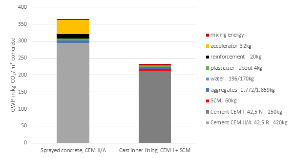


Figure 10 can be summarized by the following:
- The TBM with the standard mix designs is low in CO2 compared to 2 of the 3 NATM options. This is unsurprising as it only reflects the difference in concrete volumes (Table 1).
- The most significant CO2 reduction for the TBM tunnel, from about 6.3 tons per linear meter to about 4.3 tons (32% reduction), comes from the switch to mono-component grout (gap grout with a low cement content).
- The original NATM tunnel results in 11.6 tons of CO2 per meter, which is reduced by mix design improvements to 9.6 tons, a 17% drop.
One could conclude that the TBM tunnel will always have significantly lower CO2 levels during the construction phase, but NATM tunnels have an often-untapped potential, which will now be addressed.
Most NATM tunnels are still built assuming the primary sprayed concrete layer is only temporary and will disintegrate per definition over time, despite evidence of the opposite [10, 11]. In our example, an additional lining reserve lies in the mostly sprayed excessive thickness, the additional 150 mm, to meet the required minimum of 250 mm. Additionally, known but hardly considered, the sprayed concrete mostly overshoots the final strength requirements. Many measurements show strength well above 40 MPa (N/mm2), often above 60 MPa at 28 days, whereas 25 MPa is primarily used in design documents.
In our calculation example, the case NATM design and material optimized, the 150 mm extra sprayed concrete thickness is not considered; the hidden reserve and safety lies in the additional concrete strength and the construction and sequencing approach that the inner linings are placed after the deformations of the primary lining have leveled off. Once the primary sprayed concrete layer is considered permanent, the design assumptions for the inner lining can be questioned. In our optimized design example, the total design lining thickness of 650 mm (250 mm + 400 mm) is reduced by 1/3 (internal calculations) to get the needed inner lining thickness, which is 183 mm. It is sprayed using the same CO2-optimized mix design as the primary lining, also containing CO2 from one layer of steel mesh (AQ 70) or fiber reinforcement. No waste is assumed since wider areas can be sprayed and the rebound significantly reduced. Sprayed membranes can provide weather tightness [12].
This rather aggressive approach requires more application know-how and stricter quality control, but it lowers the total CO2 per meter to about 5.4 tons, a reduction of 54% compared to the reference. It is now in the TBM CO2 range and provides, from the CO2 perspective, more options for selecting the preferred excavation method. This approach can be questioned in many aspects, and all fairness, it isn’t meant to be copied to projects without additional considerations. Still, it should provoke additional thoughts on improvement opportunities.
6 Conclusion
The comparison of a fictitious tunnel cross-section excavated by TBM or NATM has shown that both established methods start with different CO2 levels per linear tunnel meter, with the NATM tunnel being significantly higher, primarily due to its design assumptions. Material and mix design improvements allow for a significant CO2 reduction, but the considerable reduction for the NATM tunnel requires an adjusted design approach.
Successful implementation of innovative design approaches and sustainable building materials requires owners to include sustainability targets and carbon budgets as fundamental parts of the contract documents. At best, contracts contain benefits for CO2 reduction versus a benchmark established by the designer and owner [8]. Nowadays, the purely capital cost-driven approach addresses emissions reductions as an afterthought, which is too late to make a difference.
To conclude on these considerations, the question raised in the paper’s title must be answered: Carbon-neutral tunnels can be built, but the balance to the carbon construction investment comes from the transport savings. However, to reduce the construction-related CO2 in tunnels, materials, especially concrete, play the most crucial role. The decision to deal with this challenge must not be left to the construction company; it starts with the owner and designer, choosing the proper excavation method for the geology, the CO2 budget, and establishing incentives for innovative solutions.
References
[1] Haist, M., Bergmeister K., Curbach M. et al.; 2022. Nachhaltig konstruieren und bauen Beton. Beton Kalender 2022
[2] Aldrian, W., Bantle, A., Green, D., Jakobs, A. 2021. Greenhouse gas reduction in tunnel construction: Chances and Possibilities. ITA-AITES World Tunnel Congress, WTC2022, Copenhagen 22-28 April 2022
[4] Nature. 2021. Concrete needs to lose its colossal carbon footprint, The International Journal of Science. Springer, vol.597, pp. 593-594
[5] Aldrian W, Traldi D., Fataei S., CO2 reduction in tunnel construction – focus on materials, We talked underground! ITA Slovenia, 15.-17.11.2023, Ljubljana, Slovenia, 2023
[6] Aldrian, W., Bantle, A., Juhart, J. 2022. CO2 reduction in tunnel construction from a material point of view. Geomechanik und Tunnelbau 15, H. 6, pp. 799-810
[7] Aldrian W., Bantle A., Green D., Jacobs A., 2021. Reducing the carbon footprint of segmental linings, Tunnelling Journal, April-May, pp13-21
[8] Aldrian W., Traldi D., Hernandez C., 2023, Is it possible to build tunnels with less CO2?, Tunnelling – Smart Solutions, Future Growth – TAC 2023 Conference, Toronto, Canada
[9] Sauer, J. (2016), Ökologische Betrachtungen zur Nachhaltigkeit von Tunnelbauwerken der Verkehrsinfrastruktur, Ingenieurfakultät Bau Geo Umwelt der Technischen Universität München
[10] Lorenz, S., Galler, R., (2016), “Investigations in the Field of Long-Term Stability of Tunnel Constructions,” Proceedings of the World Tunnel Congress 2016, San Francisco
[11] Galler, R., Lorenz, S., (2018), “Support elements in conventional tunneling – Focus on long-term behavior,” Underground Space, Volume 3, Issue 4, pp277-287
[12] Jung, H., Clement, F., Pillai, A., Wilson, C., Traldi D., (2017), “Composite tunnel linings, allowing a more cost-effective and sustainable tunnel design,” Proceedings of the World Tunnel Congress 2017, Bergen
Authors
Dr. Wolfgang Aldrian, wolfgang.aldrian@masterbuilders.com
Chris Moxham, chris.moxham@masterbuilders.com
Master Builders Solutions www.master-builders-solutions.com
Please see the German version of the article.